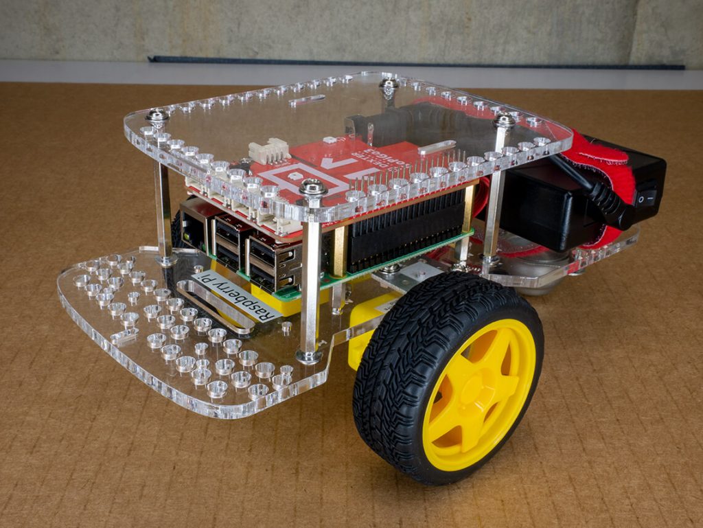
The GoPiGo has always had the option of a servo mount to scan its surroundings for obstacles. But there’s always room for improvement and we took the time to do just that.
To start, this new servo mount is much easier to assemble than our previous version. Small screws are notoriously hard for little hands. We got rid of the need for screws so more students can focus on the thinking behind their build.
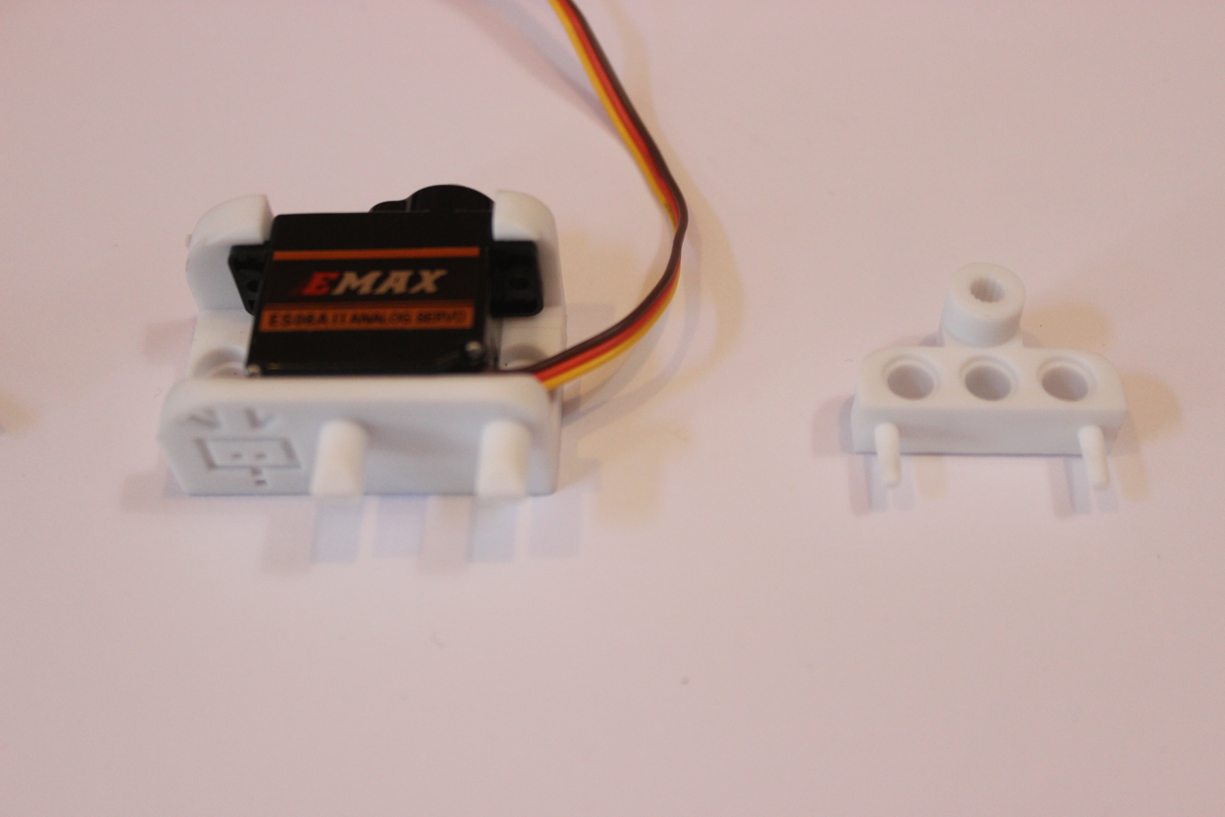
Only Two Parts
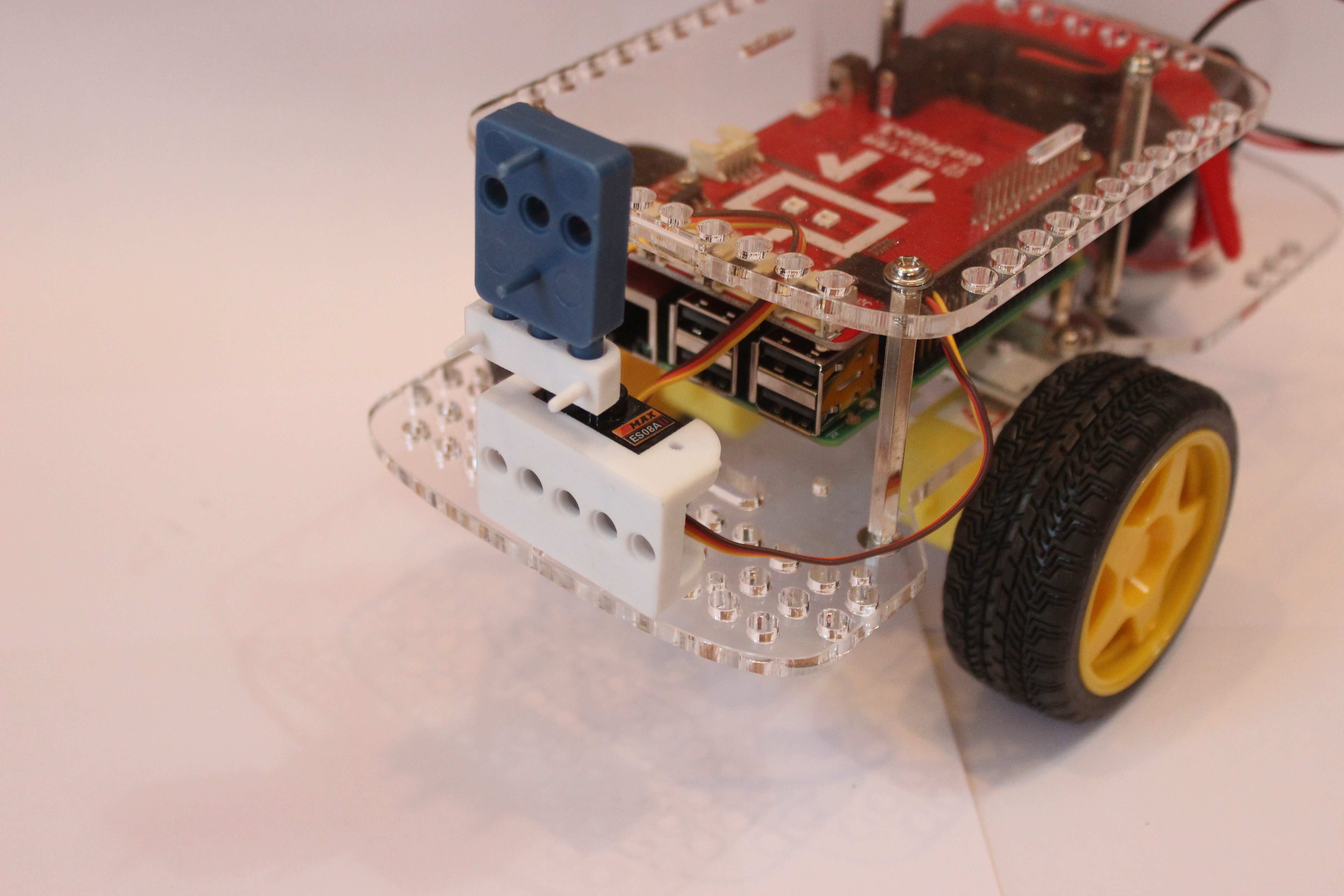
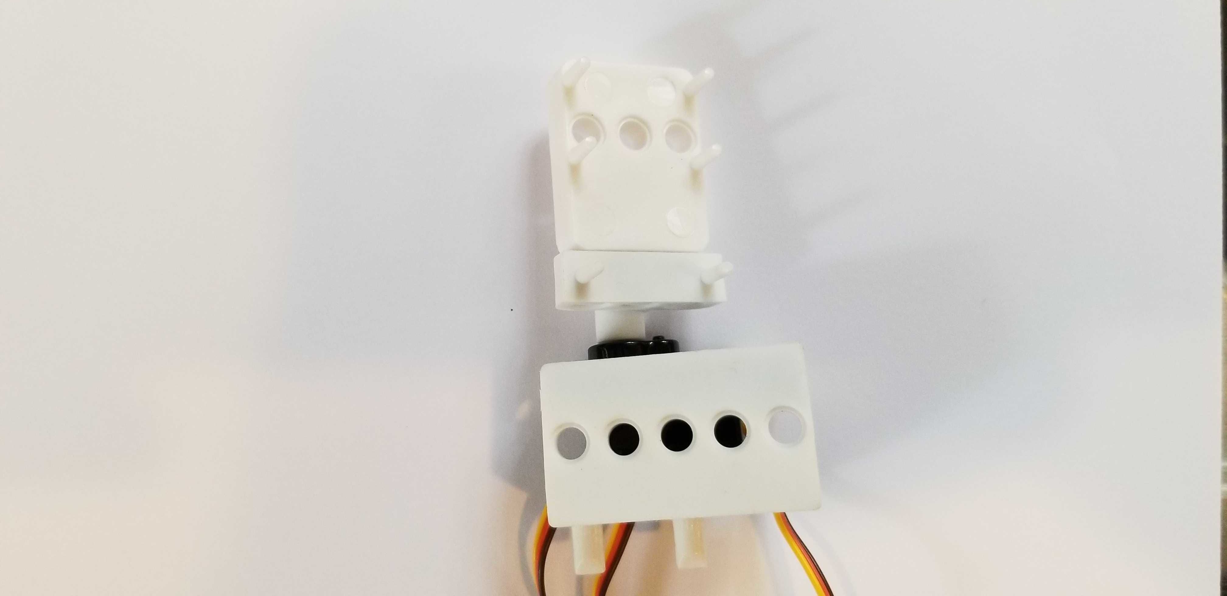
The servo mount now only comes in two sections :
- the servo mold itself containing the servo motor,
- a special servo horn that doubles as a sensor mount for the official Raspberry Pi Camera, or the distance sensor. The servo horn can also use LEGO Technic connectors, or the Dexter Industries sensor mount for added functionalities.
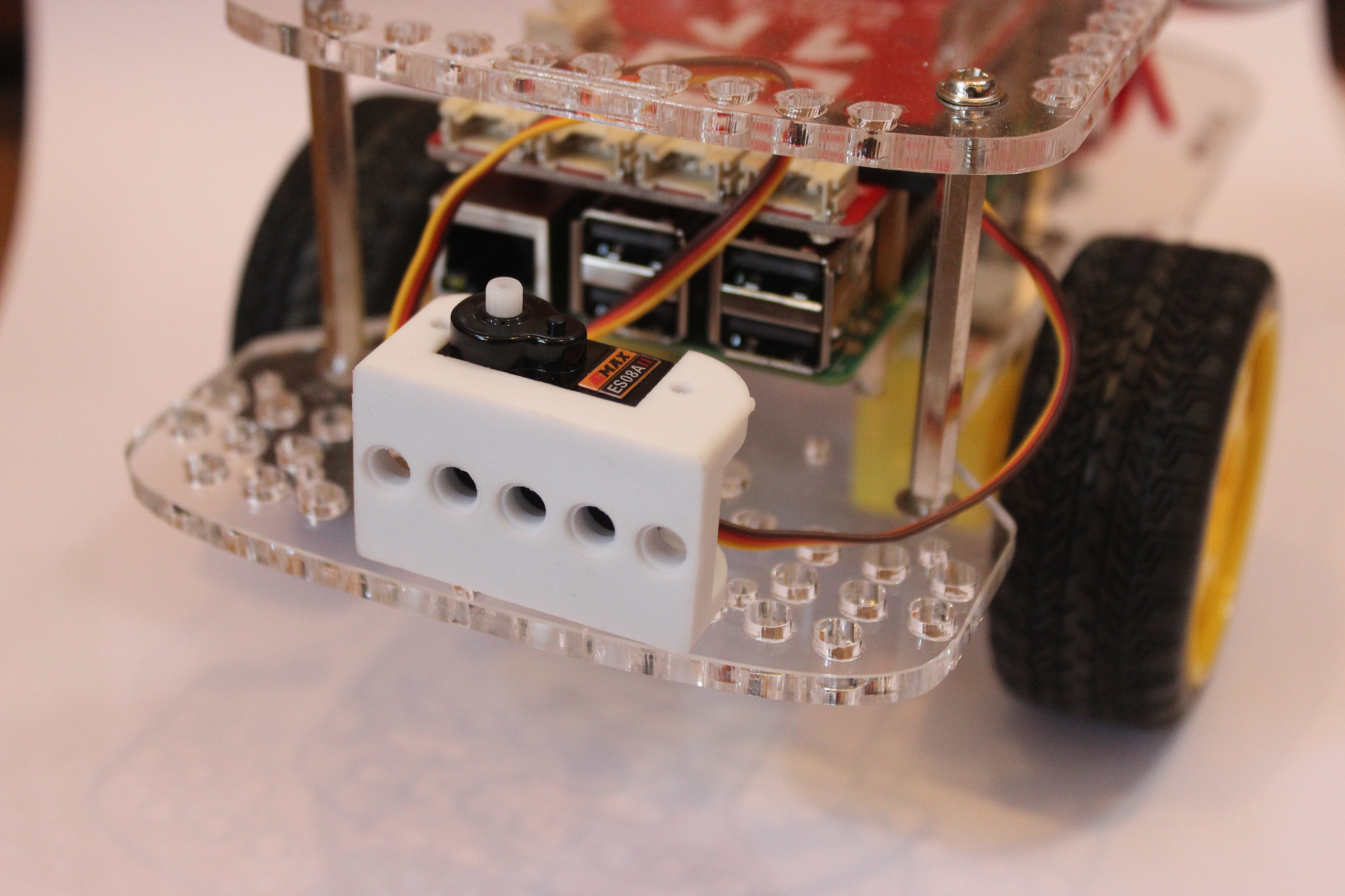
Assembly is done in just a few steps.
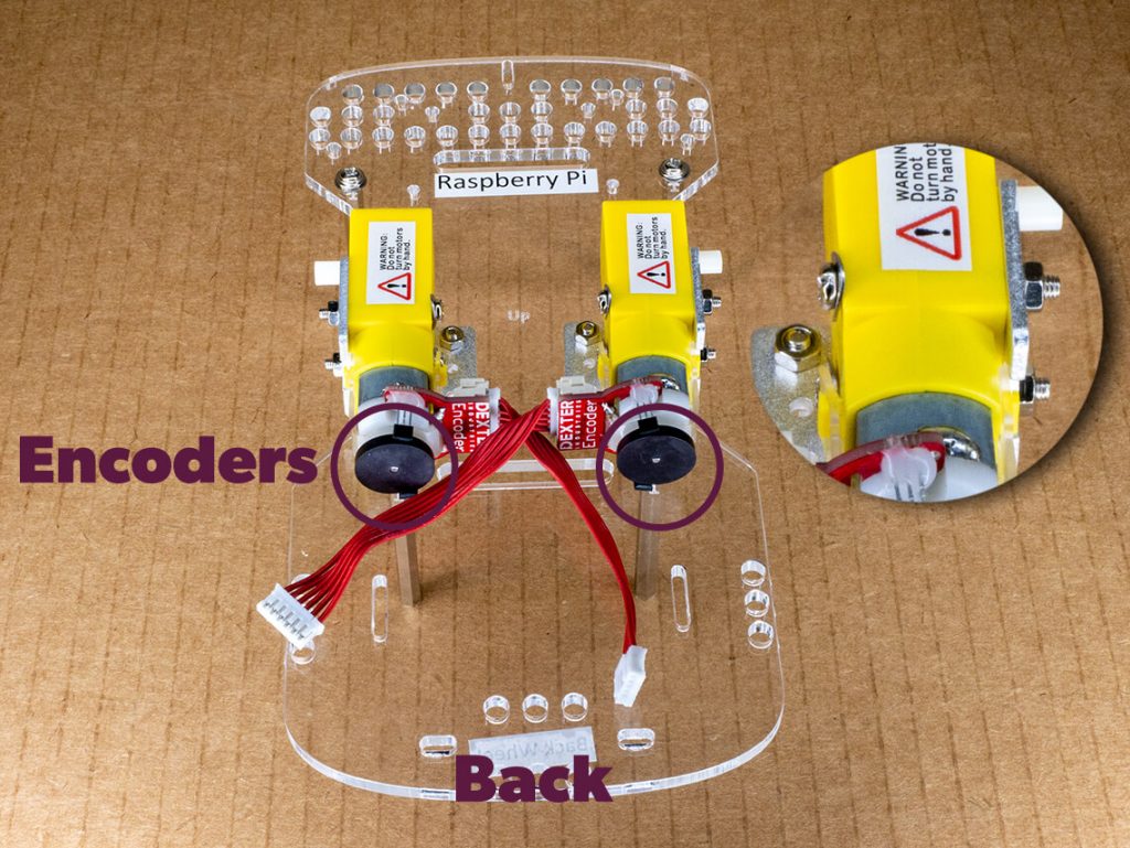
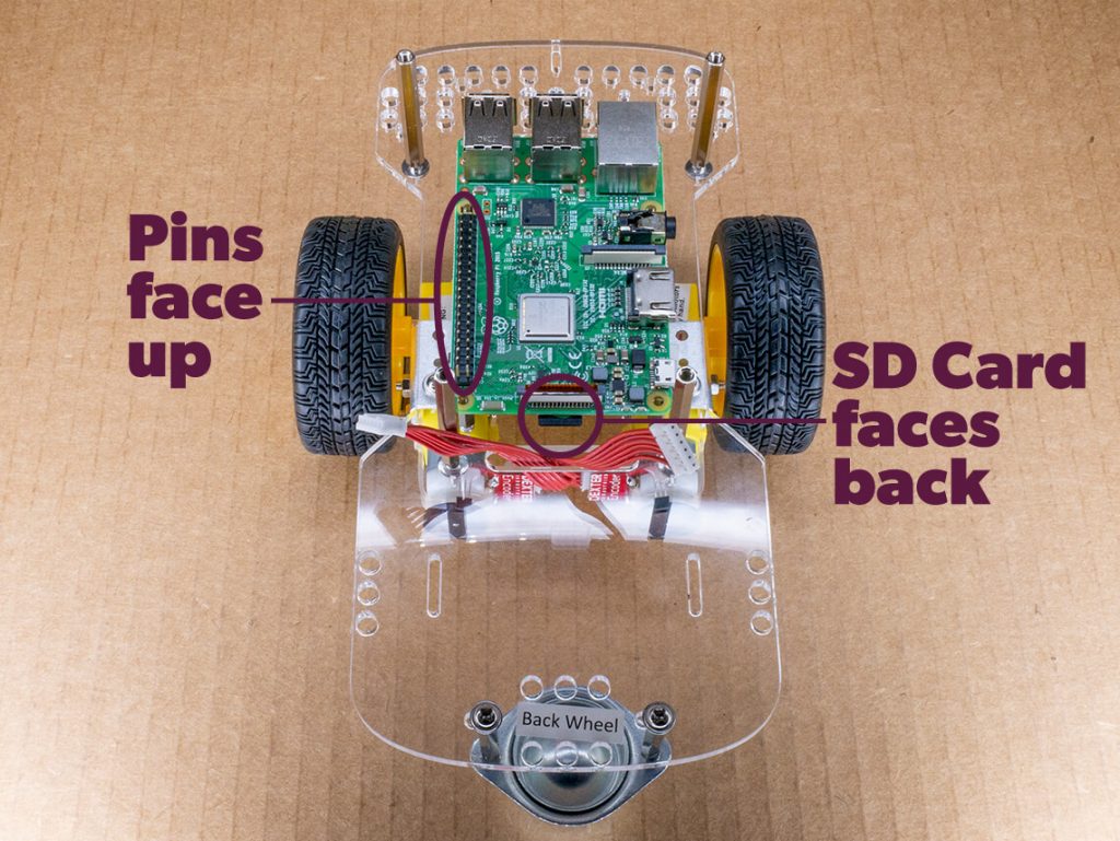
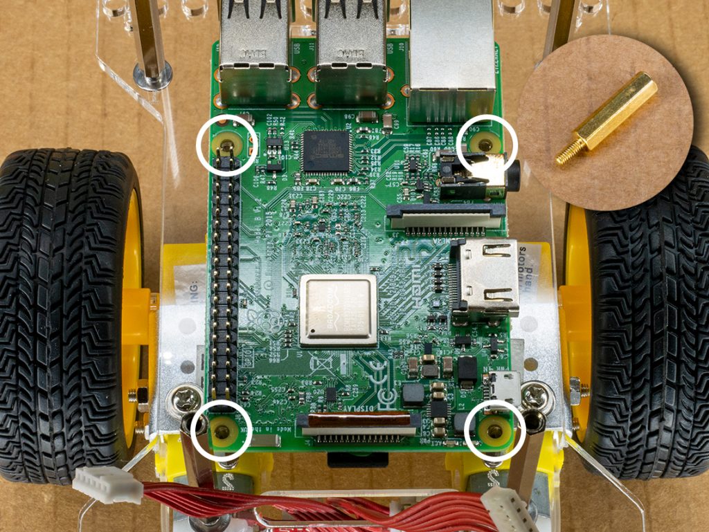
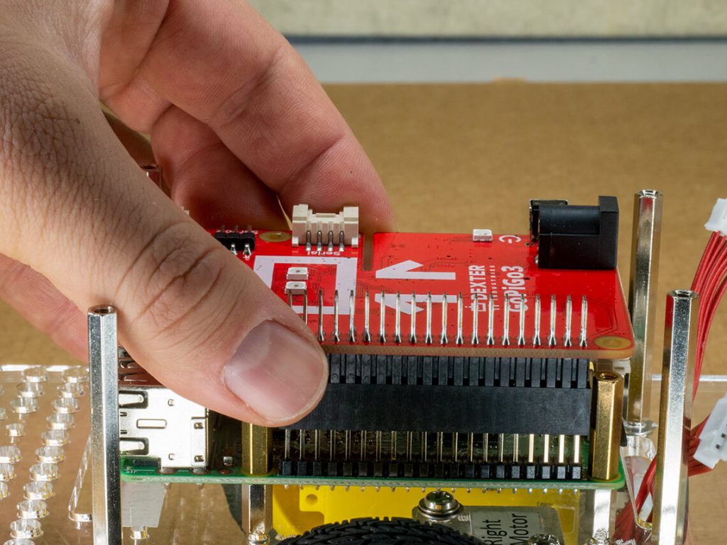
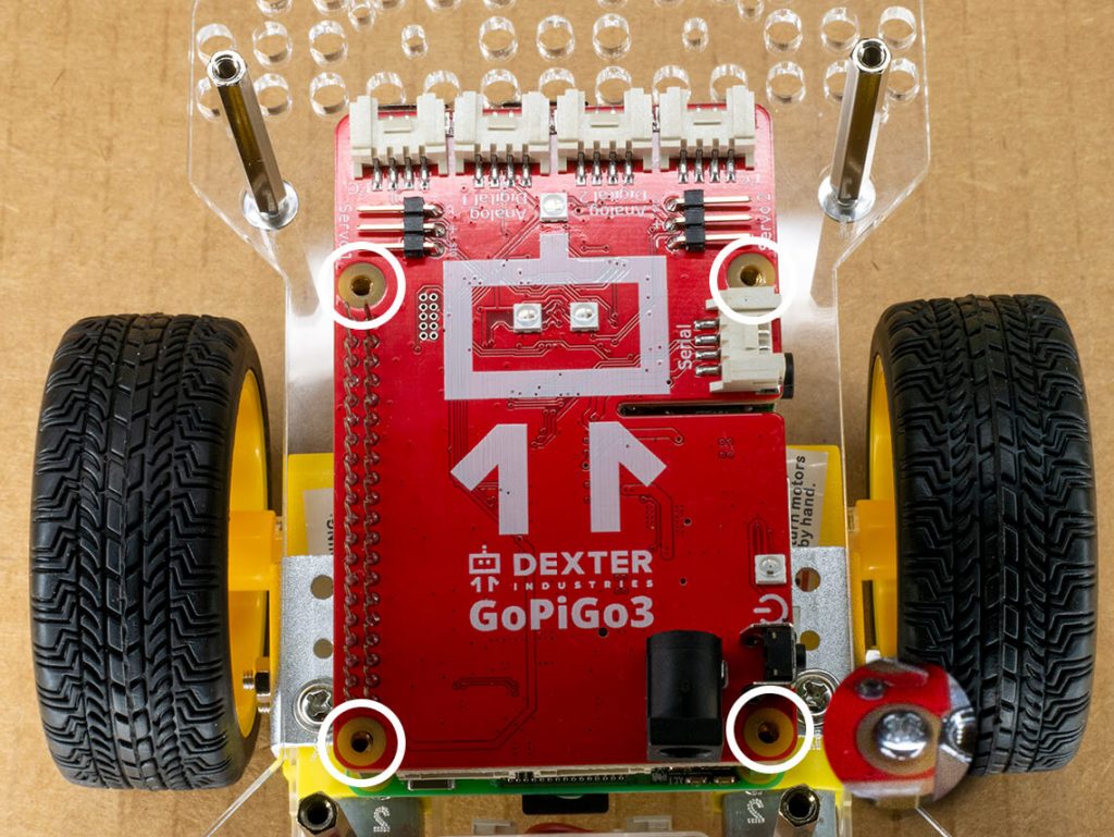
- Place the servo mold on the robot where you intend to use it,
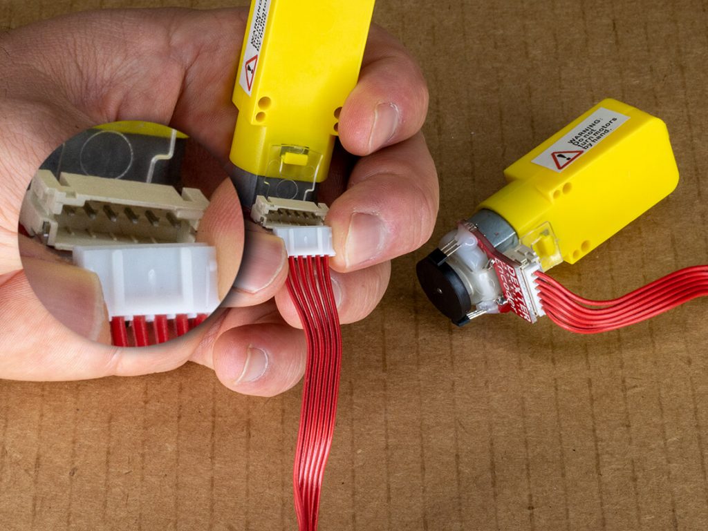
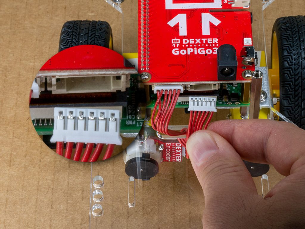
- Connect it, either to Servo 1 or Servo 2, with the brown wire to the back of the robot. The servo should twitch a little when you connect it.
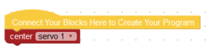
- If you are using DexterOS, go in Bloxter, and run this:
- Or if you prefer Python, run this:
import easygopigo3 as easy
gpg = easy.EasyGoPiGo3()
my_servo = gpg.init_servo(‘SERVO1’)
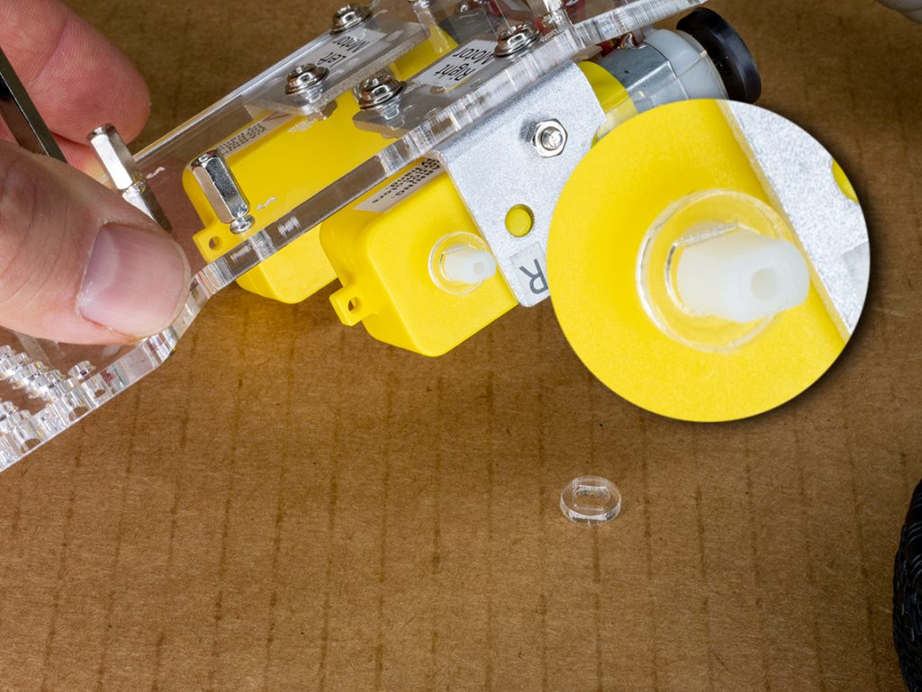
my_servo.rotate_servo(90) - Push the servo horn onto the servo itself so it is in the middle position.

That’s it. Done and calibrated.
You Want Flexibility?
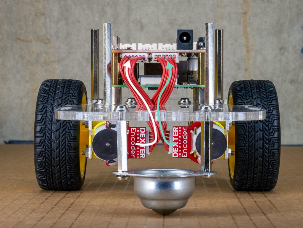
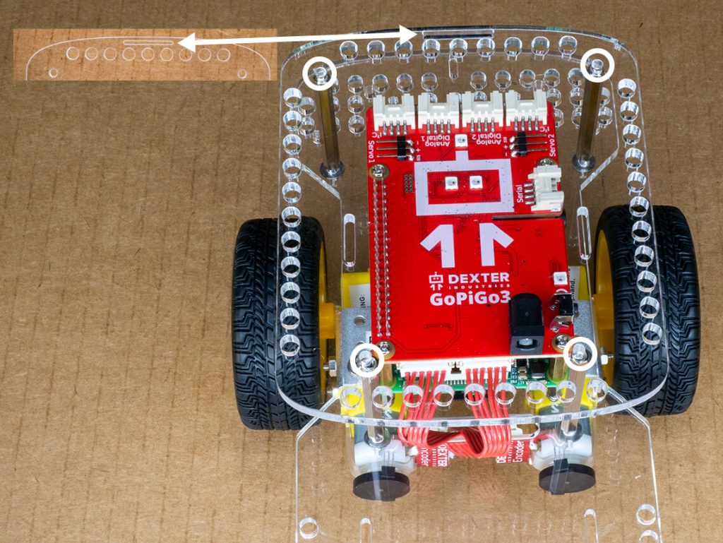
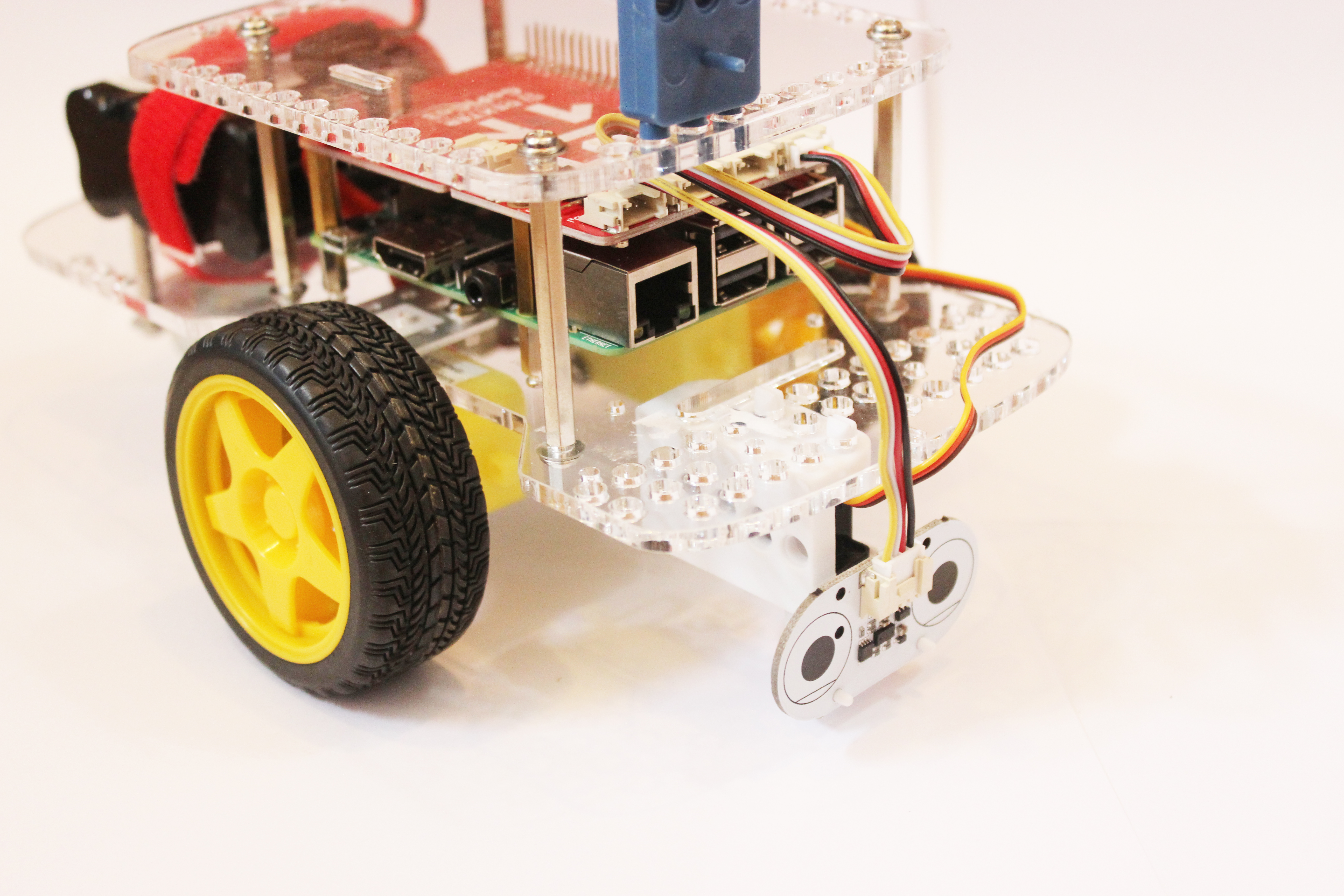
We hear you! You would prefer the distance sensor to be as low as possible in order to pick up more obstacles! Check this out… The servo mount can be installed underneath the GoPiGo3 body!
In order to have enough clearance when rotating left and right, you will need a few tweaks:
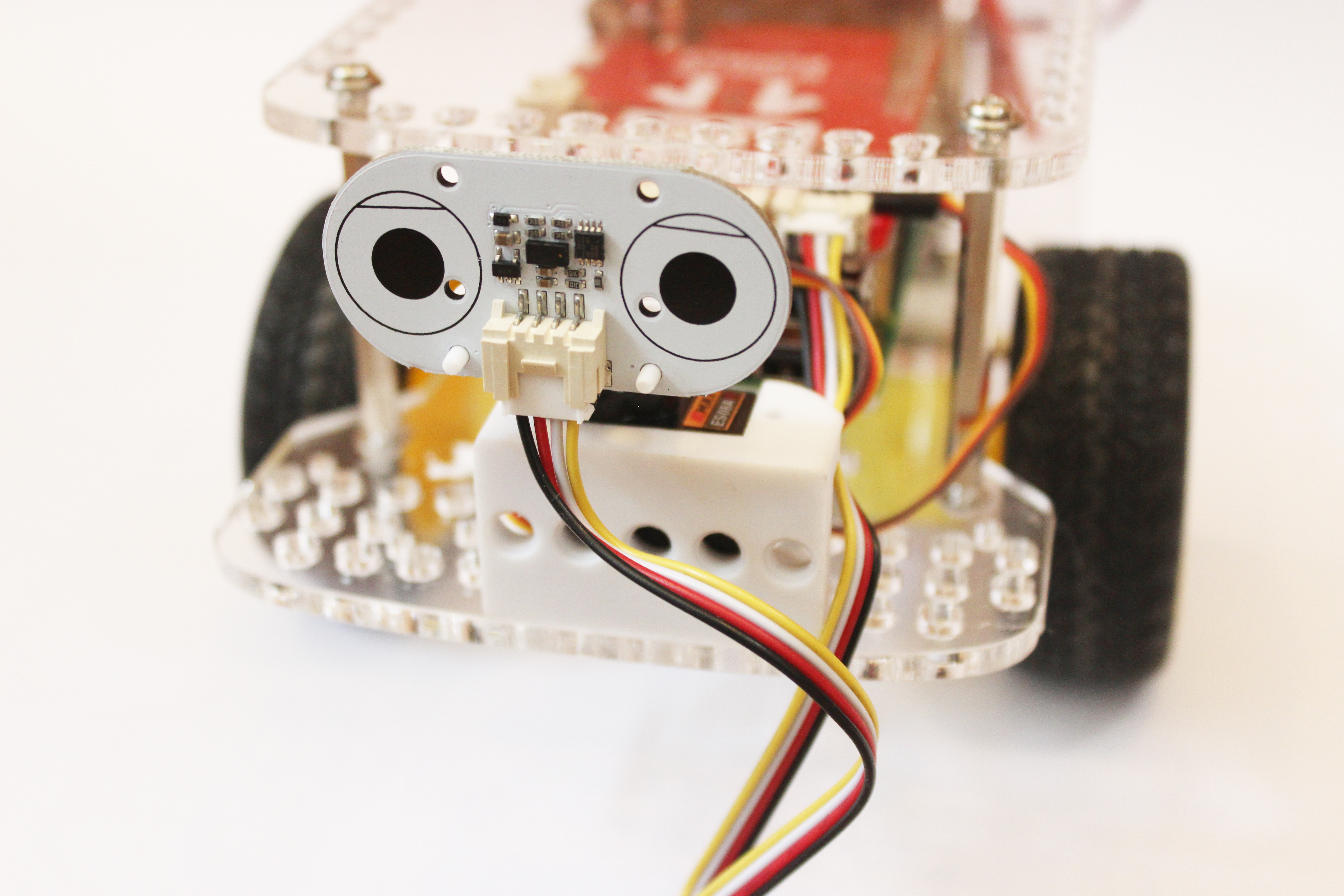
- Flip the distance sensor upside down so the connector cable is on top,
- Install the distance sensor as high as possible on the horn using the lowest holes.
- Fix the servo mold longitudinally, in other words turn it 90 degrees so that it runs parallel to the wheels.
This will get you an almost full range of motion. Do a few tests to see what the maximum angles you can get before going on with your project.
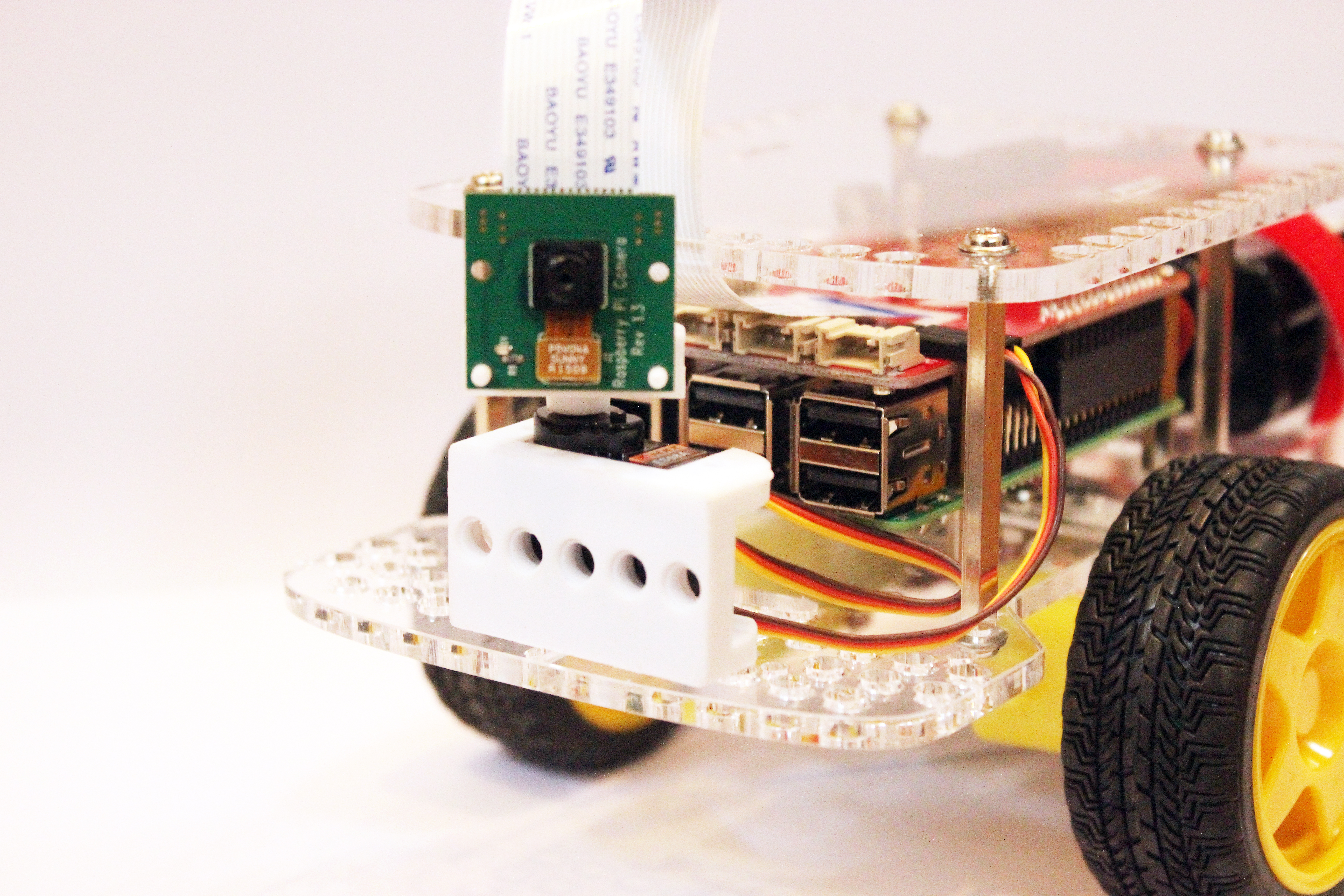
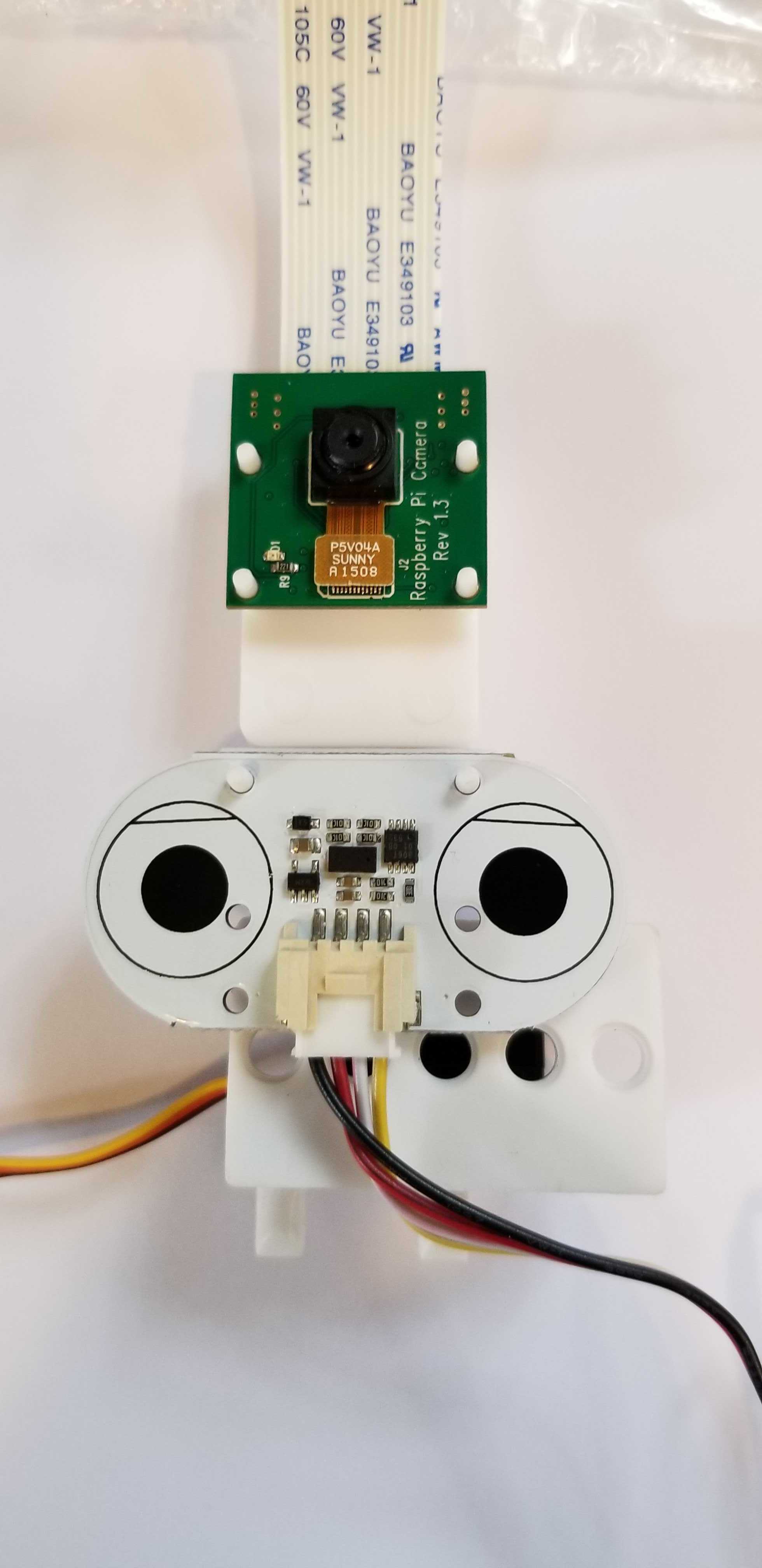
What about the Camera?
With more and more people getting into computer vision, the need for a camera that can sweep around is growing in interest.
The servo horn has been designed to fit either the Raspberry Pi camera or the distance sensor. Getting panned video is now within reach for all! We think it’s one of the easiest on the market!
As for computer vision, you can try PyImageSearch to get you started.
Even More Flexibility with a Second Sensor!
By inserting the blue sensor mount into the servo horn, you can double the servo load.
- Add a distance sensor and a camera to have them work in sync.
- Add a camera and an LED to indicate when a photo is being taken or video being recorded.
By pairing two sensors on the same servo and using some imagination you can create new interactions!
Blue Sensor Mount or White Sensor Mount?
We have a white sensor mount which has been designed specifically for the official Raspberry Pi camera, and our distance sensor. You can use the white sensor mount if you want both camera and distance sensor on the same servo.
The blue sensor mount is meant for all other Grove sensors.
Building with the improved servo package!
Both the servo mold and the servo horn allow you to build with LEGO Technic beams. You can build a stationary part and a moving part that work together while exploring mechanical engineering concepts.
Can you create a grabber?
Or whiskers that will detect obstacles by touch using button sensors?