fbpx

Getting Started Guide

GoPiGo robot with distance sensor

Attach the Wheels

Section Goal

In this section, you will attach the motors, caster wheel, and wheels to your robot.

Goal for step 3 - attach motors, cables, wheels, and caster wheel.

Attach the Motors

Parts

From the Motor Hardware Bag:

Steps

Attach the red cables to the yellow motors.

The cables will only attach in one orientation.

The GoPiGo is designed to be assembled and disassembled, so if you ever need to change the motors, you’ll be able to.

Attach red cables to motors. Only one orientation works for the cable. Do not force.

Put the washers on the screws.

Slide the long screws into the motors from the side where the wire is connected as shown in the picture.

Motors with screws threading through the holes in the motor body. Screw head should be on same side of motor as the red wires.

Turn the acrylic body over so the metal motor brackets are pointing up and the acrylic is resting on your building surface.

Assembly diagram - shows screw threading through, a washer, then motor body, then motor bracket, and then capped with the nut.

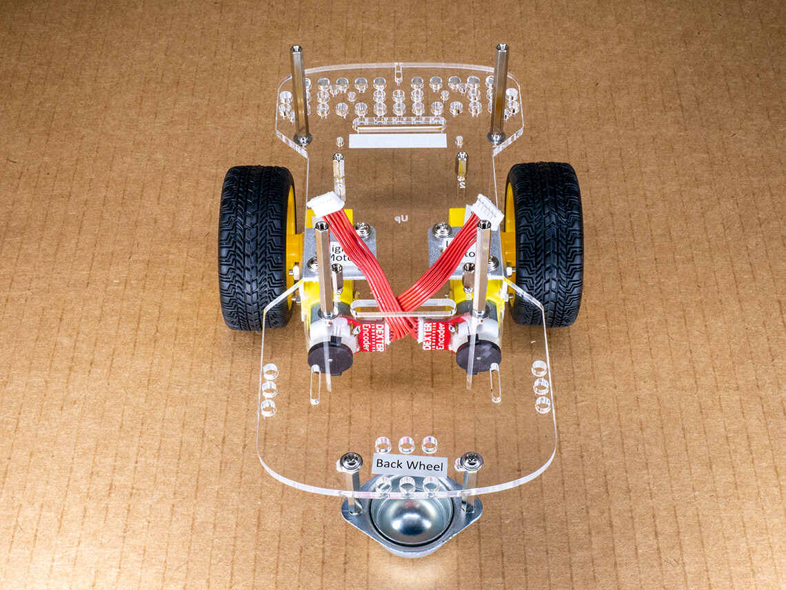
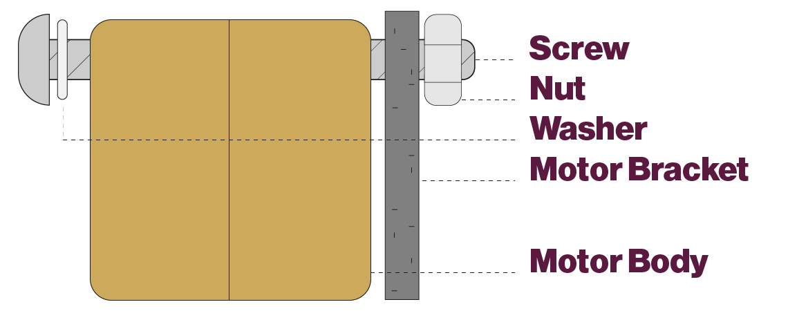
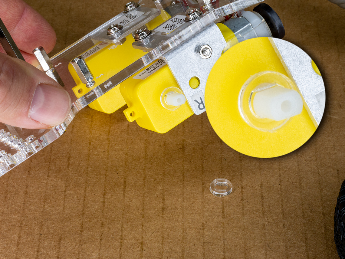
Set each yellow motor inside a motor bracket. 

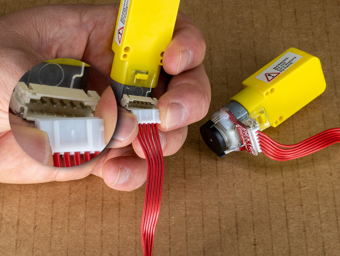
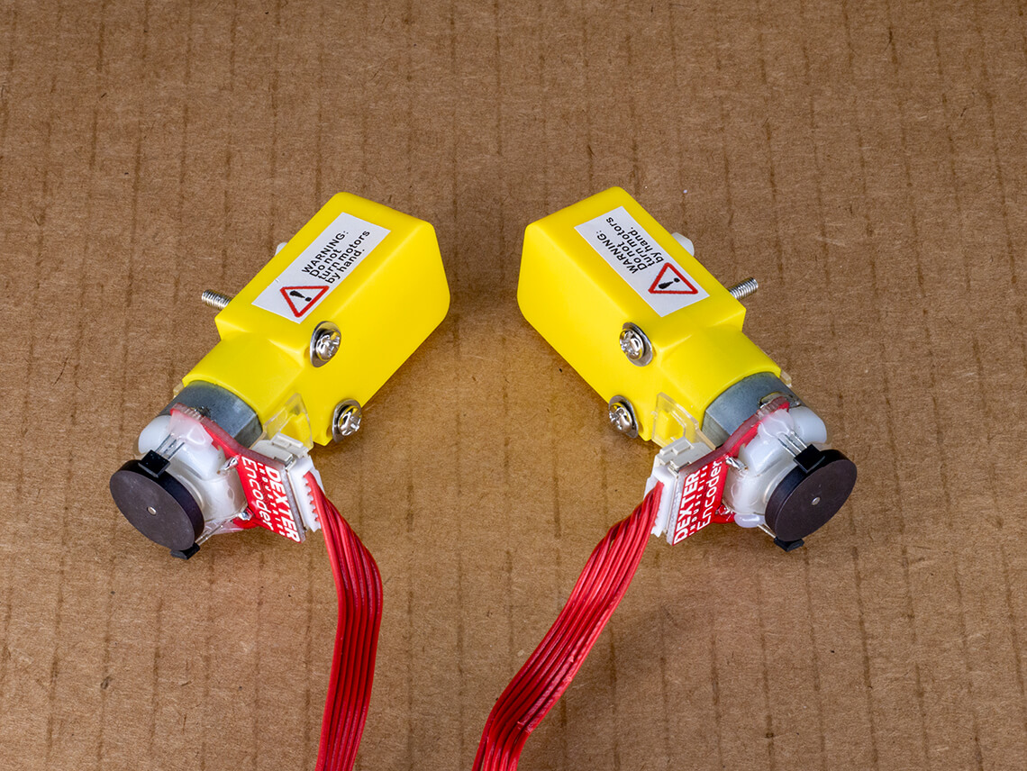
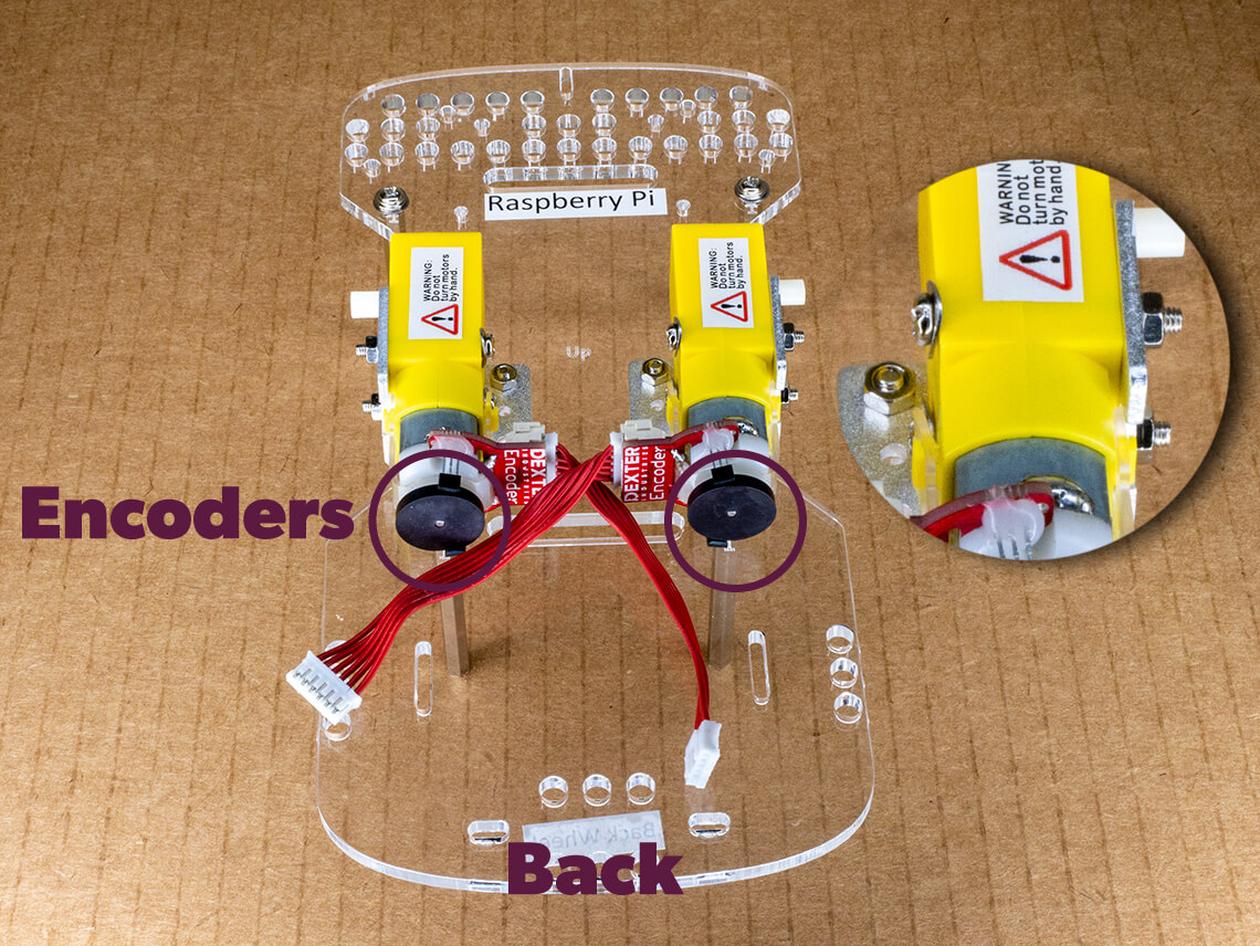
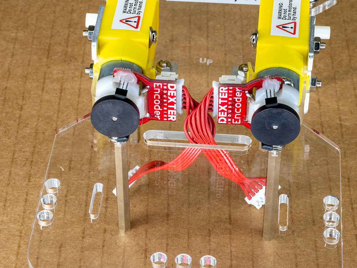
The red wires should be facing inward, nearly touching each other. 

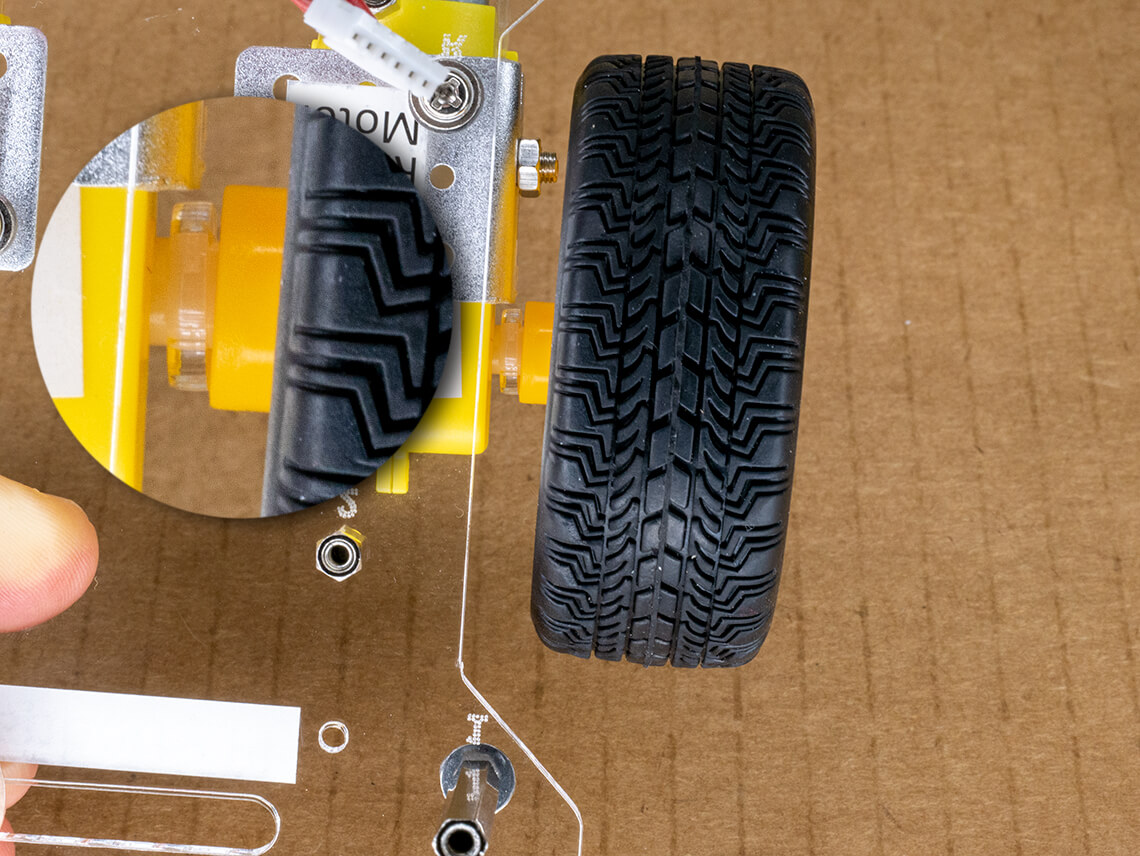
The ends of the screws should fit through the motor bracket and extend beyond the edge of your robot. 

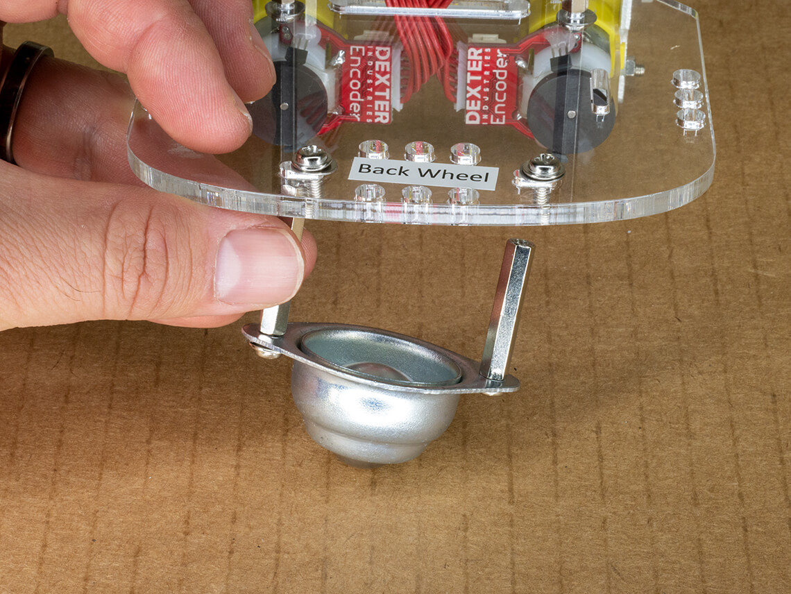
To check your work, make sure the black circle encoders are facing the back of the robot.

Motors mounted in brackets - nuts should be on outer edge of robot - black encoders should face the back of the robot.

Attach the nuts to the screws, tighten until the washers flatten.


Slide both motor cables through the acrylic board using the rectangular slot.

Red motor cables should be routed through the rectangular hole near the black encoders.

Attach the Caster Wheel

Parts

From the Caster Hardware Bag:

Steps

Place a washer on all four screws, and use two of them to screw the two medium silver posts into the caster wheel.  

The posts should stick out the opposite side from the caster wheel itself. 

Tighten until the washers are flat.  

Assembly diagram- shows a screw threading through a washer - then the caster wheel- into a post. Post should be extending away from the caster wheel.

Flip the acrylic robot body so the yellow motors are touching your building surface. At the back of the acrylic, there are two short oval holes

Slide the caster wheel underneath these holes so the wheel is touching your building surface.

Attach two screws from the top of the acrylic.

Tighten the screws until the washers are flat.

Caster wheel assembly mounts to the bottom of the robot using a screw and washer threading into the post.

Attach the Wheels

Parts

From the Motor Hardware Bag:

Steps

Wheels with acrylic spacers.

Slide the two acrylic spacers onto the white plastic axles on the motors.

Place spacer on white motor axel

Then, slide the two yellow wheels onto the axles of the motors.

Mounting the wheel to the motor axel.
Goal for step 3 - attach motors, cables, wheels, and caster wheel.